The Hall Effect
A student's casual write-up of a Hall effect lab report, covering the basics of Hall voltage, charge carriers, and Lorentz force in a way anyone can follow.
Just by looking at it, if you can tell we’re at the same school, don’t copy lolololololololololololololololololol
I’m just posting this because I want to learn a bit from people who write this kind of thing well…
This… just looking at it,,,, it doesn’t look like a report,,,, it looks like just a blog article….
Ah…… I’m agonizing over how to write this so it’s clean and so that anyone can understand it.
I’ll be waiting for comments.
Hall Effect
Date: 2016. 03. 05
Purpose of experiment: Verify the relationship between Hall voltage and magnetic field strength, and measure the polarity of the charge carriers.
In addition, measure the charge carrier concentration and mobility.
Experimental theory:
Hall Effect
The Hall effect (henceforth Hall effect) investigates a phenomenon that occurs in an object under the influence of a magnetic field.
The reason it’s called the Hall effect is that it was discovered in 1879 by Edwin Hall, a graduate student at Johns Hopkins University in the United States, and thus named accordingly.
As everyone already knows, if there is a moving charge, it is definitely affected by a magnetic field.
That it receives the Lorentz force is a fact known to everyone.
This fact was seen in a wire or a solid.
To explain with a wire, suppose charges are moving in the → direction inside a wire, and an external magnetic field is applied in the ↑ direction.
Then if they weren’t moving, they wouldn’t receive the Lorentz force, but because the charges are moving, the Lorentz force arises. Charges moving in one direction get deflected toward one side.
So there is a tendency for certain charges to gather on one side within the wire, and a relative (+) and (-) difference arises inside the wire. (It gets charged up) In this way, a new electric field is formed up and down, and this is called the Hall field.
Also, because the charges have relatively piled up on one side, they have a relative voltage difference.
This is called the Hall voltage.
This Hall field and Hall voltage are affected by the drift velocity of the charges, the sign of the particle carrying the charge, and the concentration of the particles.
ⅰ) Charge carriers
The particles that perform the role of carrying the current within a material are called charge carriers.
Charge carriers are usually electrons, but in ordinary liquids ions can also be charge carriers. And inside a semiconductor, charge can also be carried by electron holes, which arise because the outermost electron shell is not completely filled with electrons.
When electrons carry the charge, it can be seen as (-) charge flowing, and when holes carry the charge, it can be seen as (+) charge flowing.
But the fact that current flows is essentially the free electrons moving.
Therefore, in both cases, if they are under the influence of a magnetic field, they unfailingly receive the Lorentz force.
However, because the mechanism by which they flow is different, we distinguish ’electrons carry it’ from ‘holes carry it’.
ⅱ) Lorentz force
A moving point charge receives a force under a magnetic field. Letting the magnetic field be the vector B and the direction and magnitude of motion be the vector v, the force due to the magnetic field is

. And the Coulomb force due to the electric field also exists.

Combining the two forces,
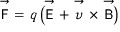
this is called the electromagnetic force or the Lorentz force.
ⅲ) Hall effect experiment
The phenomenon in which, when there is a sample with current flowing in it inside a magnetic field, the charge carriers pile up on one side and a Hall voltage arises, was discovered by E. H. Hall in 1879. By this Hall effect, one can know the sign and the concentration of the charge carriers inside the sample.
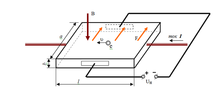
[ Figure 1 ]
( Source: http://katastrofy-phisics.narod.ru/Hall_en.html )
Thinking of the case when the sign of the charge carriers is (-)(negative), look at the experimental design diagram as in [Figure 1].
As in the figure, the current flows to the left, and the magnetic field is incident perpendicularly from sky to ground.
By the electromagnetic force, the negative charge carriers pile up to the right with respect to the direction of travel, and as these charge carriers accumulate on the right side of the direction of travel, a potential difference, the Hall voltage, will arise.
Once steady state is reached, the force due to the electric field from this Hall voltage and the electromagnetic force cancel out, and the charge carriers move only in the forward direction, so the current will flow only in the forward direction.
Writing this as an equation, it is steady state, and because the magnetic field is incident in the perpendicular direction,

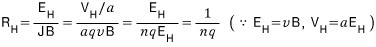
we can obtain this equation. And if the width of the sample is a, then the Hall voltage

is

we can obtain this.
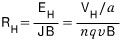
Here,

is what’s called the Hall field, and what you get by dividing this by the product of the volume current density and the magnetic field is defined as the Hall coefficient.
The meaning of the Hall coefficient is the value that determines the strength of the electric field produced by the Hall effect. That is, the Hall coefficient value is a characteristic that is uniquely determined for each sample.
The Hall coefficient

can be organized as follows.
multiply by the thickness b as

like this. Then
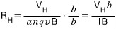
we can write it as.
Also,
Through this equation, if we know the Hall coefficient we can find the charge carrier concentration n.
Once we find the charge carrier concentration n in that way, we can find the mobility as below.
The current density is
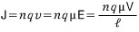
. What to watch out for is that we need to be careful about V and E, which are distinct from the Hall voltage and the Hall field. Here n is the concentrashun of the charge carriers and μ is the mobility is. Therefore, if we know n, we can find μ.
ⅳ) Van der Pauw law
Although [Figure 1] is the ideal Hall measurement situation, experimentally it is not easy to make the current flow only in the forward direction.
So Van der Pauw, using conformal mapping, developed a method for measuring the electrical conductivity and Hall coefficient of a sample with a non-uniform shape.
He showed that if the following 4 conditions are satisfied, then without knowing the pattern of the current, one can determine the resistivity, carrier concentration, and mobility of a sample with an arbitrary shape and a uniform thickness.
① The contacts are on the boundary of the sample. ② The contacts are sufficiently small. ③ The thickness of the sample is uniform. ④ The surface of the sample is singly connected. (There is no empty space inside the sample.)
References
[1] Harald Ibach, Hans Luth / Solid-State Physics / trans. Park Hong-i / Sciteq Media (2010) / p 456 – p 458 /
[2] Naver Encyclopedia / “Hole”, “Hall coefficient”, “E. H. Hall” / http://terms.naver.com/ / 2016. 3. 5. /
[3] “Lorentz force” / http://gdpresent.blog.me / 2016. 3. 5.
Originally written in Korean on my Naver blog (2016-03). Translated to English for gdpark.blog.